 AH-1Z
AH-1Z
 AH-64
AH-64
 C-17
C-17
 CH-47
CH-47
 CH-53K
 E-2C
E-2C
 F-15
F-15
 F-16
F-16
 F-22
F-22
 KC-10
KC-10
 MISC
MISC
 UH-60
UH-60
 UH-72
UH-72
 V-22
V-22
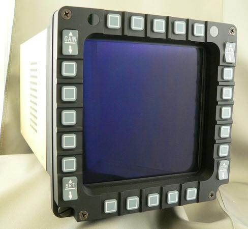 F-16 Color Multi-Function Display
The MFD is a simulated version of the 4 X 4 inch Color Multi-Function Display as used in the F-16 aircraft. It is intended for training and simulation purposes only.
The front appearance is a high fidelity duplicate of the original flight instrument, including the fully functional switch bezel and the AMLCD display. The AMLCD back-light and the bezel illumination meet NVIS requirements as specified in MIL-STD-3009.
The high resolution (768 by 768 pixel) AMLCD is custom manufactured by resizing a commercial AMLCD panel from a 4 X 3 aspect ratio to a square format. The unit is ruggedly built to take the most demanding simulation environments. It is one of a wide family of cockpit simulation products designed and manufactured by Panel Products Inc.
Video rate: 1024 by 768 pixels, (XGA) 48.3 KHz horizontal by 60 Hz vertical. The horizontal displayed image is a 768 pixel "cut out" section of the 1024 horizontal pixels available. It can be the right, left, or center portion, as selected by the internal video processor.
Video input connector: Standard 15 pin high density D type with separate R, G, B, H, and V inputs. The unit can accept all sync formats, separate H and V, Composite H and V, and Sync on Green.
Display technology: Resized commercial AMLCD with NVIS filtered white LED backlight Viewing angle is +- 80 degrees in both horizontal and vertical directions.
| Environmental: | Operating | Storage |
| 1. Temperature | 10 to 35C | -20 to 65C |
| 2. Humidity | 20 to 90% | 0 to 95% | 3. Shock/vibration | Suitable for ground benign and motion based trainers. |
Power requirements: AC - 85-240 VAC, 47-63 Hz, power consumption 30 watts. Standard IEC 320 type receptacle. DC Voltage operation is available as an option, 20-32 VDC, (Unit is protected internally from accidental voltage reversal).
Bezel:
1. Twenty SPST momentary contact push buttons plus four SPDT momentary contact rocker switches. The switches are interconnected in a matrix format and direct connections to the matrix are available at the rear panel. Alternately, as an option, the bezel operation can be encoded into a serial data stream in RS232, RS422, or RS485 format.
2. Bezel backlight is NVIS compatible and is operated from 0 to 5 VDC or VAC at 3 amps maximum. Electrical connections to the backlight are available at the rear panel.
I/O connections, at rear panel of display:
1. J1 - Bezel interface connector, 26 pin high density "D", female sockets.
2. J2 - Video maintenance port, 9 pin "D", female sockets.
3. J3 - Video input connector, 15 pin high density "D", female sockets, standard VGA type connections.
4. J4 - AC power connection, standard IEC 320 input module with integral fuse and ON/OFF switch.
Other rear panel:
1. Power on LED, green.
2. Video presence and status LED, bi-color.
3. Cooling fan, draws air into unit from back, exits out both sides and top.
Physical:
1. Image area: 5.52 inch diagonal, 3.90 inch wide by 3.90 inch high.
2. Front bezel: 5.60 wide by 5.60 high by 0.51 thick.
3. Size behind bezel: 5.22 wide by 5.13 high by 9.03 deep.
4. Weight: 5.6 lbs.


 Manufacturer of Simulation Displays &
Lighted Panels (310)830-3331
 Contact
Contact
About
About
Home
Home
Products
Products
Services
Services